The three contaminants have opposing chemical properties, and no single chemistry removes all of them. To finish in one loading, the line must be staged: solvent or emulsifying stage for oil, water-based stage for carbon black and coolant, and pure water stage to displace dissolved residues, using multi-frequency ultrasonics and inter-tank isolation instead of repeated single-tank cycles.
“Removal in one pass” means the workpiece is loaded and unloaded only once while the entire sequence runs continuously on one line. It does not mean putting all contamination into a single tank with one set of parameters. Aviation lubricant is an oil phase with high viscosity and strong metal affinity. Carbon black is a solid particulate with large specific surface area that only adheres firmly once wrapped by an oil film. Coolant is a water-soluble system containing surfactants and extreme-pressure additives, and its residues are removed by displacement during rinsing. The removal mechanisms differ, and forcing them into one tank produces predictable failures: oil is not fully stripped before entering the water-based stage, carbon black is re-adhered by emulsified oil, and coolant remains trapped in blind holes because rinsing is insufficient.
Conflicts concentrate in three areas. First, medium conflict: removing lubricant requires an oil-phase-capable or strongly emulsifying chemistry, while removing coolant and carbon black residues requires an aqueous system with good rinsing behavior. In one tank the two form an emulsion, and dispersed oil becomes even harder to discharge from blind holes. Second, frequency conflict: carbon black and thick oil films need low-frequency, high-intensity cavitation for layer break-up, while precision surfaces and blind holes require high frequency at restrained power density. A single tank can only take a compromise value, and a compromise leaves both ends short of target. Third, temperature conflict: the oil phase benefits from higher temperature to reduce viscosity, but excessive temperature in the water-based stage accelerates detergent hydrolysis and foam generation, weakening cavitation intensity.
The engineering answer is to separate the chemical stage from the physical stage: an oil-capable tank removes the bulk oil load, an aqueous tank with surfactants disperses particulate carbon, and multi-stage pure water displaces dissolved residues. The success of mixed-contamination cleaning depends less on ultrasonic power than on tank sequencing: oil must be removed in its own tank and must not be carried into the carbon black stage.
| Contaminant | Physicochemical Property | Compatible Medium | Dominant Removal Mechanism | Key Parameters | Main Risk |
|---|---|---|---|---|---|
| Aviation lubricant | Synthetic ester, high viscosity, strong affinity | Hydrocarbon solvent or weakly alkaline aqueous with strong emulsification | Dissolution / emulsification + cavitation stripping | 45–60 ℃, low frequency 28 kHz | Volatilization loss at high temperature; hard to rinse after aqueous emulsification |
| Carbon black | Solid particulate, large specific surface area, wrapped by oil film | Aqueous surfactant system | Low-frequency cavitation break-up + dispersant suspension | 60–65 ℃, 25–35 W/L | Stripped particles re-settle and re-adhere |
| Coolant residue | Water-soluble, contains surfactants and EP additives | Aqueous + multi-stage pure water rinsing | Dilution + displacement (not drying) | Final stage conductivity ≤5 μS/cm | Retention in blind holes, film formation after drying |
The values below are engineering reference ranges. Final parameters must be locked through sample cleaning tests.
| Tank Position | Frequency | Reference Power Density | Temperature | Duration | Primary Function |
|---|---|---|---|---|---|
| Pre-wash | None or 28 kHz | — | 50–60 ℃ | 1–5 min | Remove floating oil and thick sludge |
| Main cleaning | 28 kHz | 25–35 W/L | 60–65 ℃ | 10–15 min | Break oil film, strip carbon black layers |
| Fine cleaning | 40/68 kHz | 10–15 W/L (transducer surface 0.3–0.5 W/cm²) | 55–60 ℃ | 5–10 min | Clean blind holes, protect precision surfaces |
| Rinsing | 40 kHz (optional) | 5–8 W/L | Ambient–45 ℃ | 1–2 min per stage | Assist displacement of cavity residues |
| Drying | — | — | 70–90 ℃ | 10–15 min | Water removal, prevent recontamination |
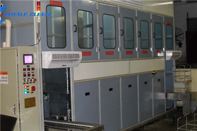
Reference inner tank dimension: 800×500×600 mm, effective liquid volume ~200 L. At 30 W/L for main cleaning, ultrasonic power is about 6 kW; at 12 W/L for fine cleaning, about 2.4 kW. A six-tank line is typically 12–16 m long including loading and drying sections. With 500×400×300 mm baskets and a cycle time of 20–30 min per basket, throughput reaches 2–3 baskets per hour; when capacity is short, add parallel main cleaning tanks or a dual-station loader. Do not trade throughput for fewer rinsing stages or higher main-cleaning temperatures. Fewer rinsing stages simply leave oil and coolant residues back on the parts.
Q1: Can one detergent remove all three contaminants?No. Oil-phase and aqueous chemistries conflict; mixing them forms an emulsion that is harder to discharge from blind holes.
Q2: Is drying required between the solvent stage and the aqueous stage?Drainage or pre-drying is needed to prevent solvent carryover into the aqueous tank, which would shift detergent concentration and weaken cavitation.
Q3: Black water still flows from holes after cleaning. What is the cause?Particles remain trapped in cavities. Agitation, flipping or directional spray must be added in the fine cleaning and rinsing stages.
Q4: Can aluminum parts go through the high-temperature aqueous stage?Only under controlled conditions: 55–60 ℃, pH ≤10 and shortened contact time, otherwise alkali etching and darkening occur.
Q5: How to verify that all three residues are removed?Use itemized acceptance: white cloth wipe for oil and carbon black, borescope inspection of galleries, and final rinse conductivity for coolant residue.
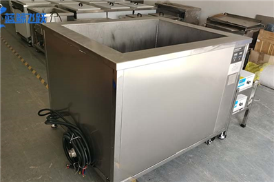
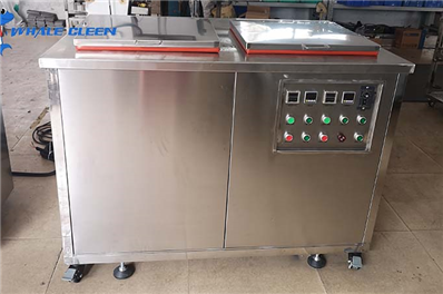
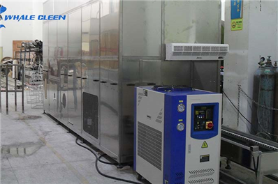
Whale Cleen supplies single-tank, multi-tank and fully automatic ultrasonic cleaning lines, configured with solvent and aqueous stages according to contamination stratification, with isolation, drainage and anti-carryover structures between stages. Automatic lines use gantry or robotic transfer. The PLC recipe library stores frequency, power density, temperature, duration and rinsing stages for each tank per part type, and logs bath temperature, liquid level and final rinse conductivity so that process parameters can be correlated with inspection results.
Non-standard customization is defined by four inputs: part drawing and material, relative proportion of the three contaminants, cleanliness acceptance method and limits, target cycle time and site constraints. Engineers specify tank quantity and sequence, frequency scheme (28/40 or 28/68 kHz segmented), solvent recovery and vacuum drying options, rinsing stages and overflow logic, fixture and tooling design. For one-loading removal of three contaminants, the standard approach is stage isolation for the oil phase, separate main and fine cleaning tanks, and two-stage countercurrent rinsing with agitation so that oil is not carried downstream.
Delivery workflow: sample cleaning test with itemized residue data → scheme and cycle time calculation → factory acceptance test → on-site installation and parameter reproduction → operation and maintenance training → spare parts and periodic service. If your workpieces carry aviation lubricant, carbon black and coolant residues at the same time, share the material, contamination description, acceptance method and capacity target. We will run sample tests and use itemized measured data to determine tank sequence and frequency configuration before discussing equipment.
Note: Reference values including low-frequency selection for heavy carbon and thick oil films, 40 kHz and above for precision and thin-wall parts, power density ranges, the effect of high-temperature pre-soaking on shortening ultrasonic time, hydrocarbon process frequency and temperature, and final rinse conductivity limits are sourced from public process documents. Power density W/L is defined as ultrasonic power divided by effective tank liquid volume. Tank quantity, cycle time and temperatures in this article are engineering ranges requiring validation through sample tests. They do not guarantee cleanliness for any specific workpiece.